What is a thermal imaging inspection of an electrical installation?
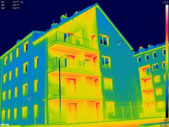
A thermal imaging inspection is a non-contact diagnostic survey carried out while electrical equipment is operating. A thermal imaging camera records surface-temperature patterns, helping the thermographer identify anomalies that may require further technical assessment.
The inspection records the condition of accessible components at the time of the survey. It can support preventive maintenance, fire-risk management and decisions about further testing or repair. It does not replace the electrical measurements required by law or by the site’s maintenance procedures.
Standards and guidance relevant to electrical thermography
The reference documents used for a survey depend on the installation, the commissioning party and the purpose of the inspection. Documents that may be relevant include:
- ISO 18434-1 — thermography used in condition monitoring and diagnostics of machines,
- ISO 18436-7 — qualification and assessment of personnel who perform machinery condition monitoring using thermography,
- IEC TS 62446-3 — outdoor infrared thermography of photovoltaic modules and plants,
- ASTM E1934 — infrared examination of electrical and mechanical equipment,
- VdS 2858 and VdS 2859 — guidance and recognition requirements used in electrical thermography,
- APSAD D19 — guidance for infrared thermography inspections of electrical installations.
No single document in this list applies automatically to every installation. Before the survey, the parties should agree which procedure and reporting requirements apply to the commissioned scope.
What can be included in the inspection?
The survey may cover low-voltage equipment and selected medium- or high-voltage equipment that is optically accessible to the camera.
Typical items include:
✔ switchboards and electrical cabinets
✔ cable connections and terminals
✔ contacts in electrical apparatus
✔ busbars
✔ transformers and instrument transformers
✔ electric motors
✔ power cables and cable bundles
✔ components of power-factor correction systems
The final scope should identify the equipment to be examined and any areas that cannot be accessed safely.
Conditions required for a useful survey
For a thermogram to be diagnostically useful, the operating and measurement conditions must be recorded and considered during interpretation.
Representative electrical load
The installation should be examined under a stable load that is representative of its normal operation and suitable for the selected procedure. The required load cannot be reduced to one universal percentage; it should be agreed for the installation and the purpose of the survey.
Optical access
The camera must have a clear view of the components being assessed. Covers may be removed only by appropriately authorised electrical personnel and in accordance with the site’s safety procedures.
Measurement parameters
The thermographer should consider the parameters that can affect the recorded temperature, including:
- surface emissivity,
- reflected apparent temperature,
- air temperature and humidity,
- measurement distance,
- the load and operating state of the equipment.
Safety
The survey itself is non-contact, but it is carried out near energised equipment. Required approach distances, site rules and the responsibilities of authorised personnel must therefore be established before the inspection begins.
Thermal imaging equipment
The camera must be suitable for the temperatures, distances, target sizes and diagnostic purpose involved. Relevant characteristics include detector resolution, measurement accuracy, thermal sensitivity, available lenses, adjustable compensation parameters and current calibration or verification records.
One of the cameras used by TERMOCENT is the FLIR T1020:
| Object temperature range: | −40°C to 2,000°C |
| Infrared resolution: | 1,024 × 768 pixels |
| Thermal sensitivity (NETD): | <0.02°C at 30°C |
| Accuracy: | ±1°C or ±1% at 25°C within the ranges specified by the manufacturer |
| Spectral range: | 7.5 to 14 µm |
| Lens: | 45° |
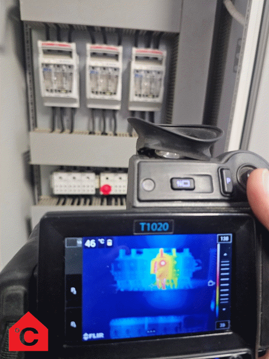
The required equipment specification should be checked against the procedure adopted for the survey. A camera’s specification alone does not determine the quality of the inspection: measurement conditions, personnel competence and interpretation are equally important.
How are the results assessed?
The thermographer assesses temperature patterns in the context of the component’s design, load and operating conditions. The analysis may include:
- comparison with a similar component operating under a comparable load,
- temperature rise relative to a reference,
- absolute component temperature,
- temperature asymmetry in three-phase systems,
- an unusual temperature distribution.
A higher temperature is not, by itself, a complete diagnosis. The cause and urgency of an anomaly should be assessed using the adopted procedure and, where necessary, additional electrical measurements or technical inspection.
Classification and repair priorities
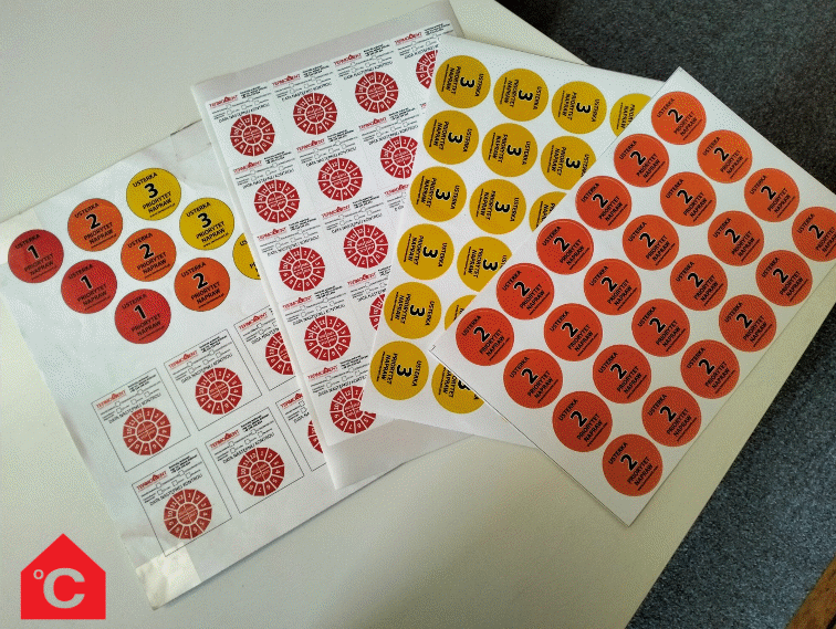
Different procedures may use different thresholds and priority classes. The report should therefore name the classification method, explain the criteria applied and relate the recommendation to the equipment’s operating conditions.
Instead of relying on a universal temperature table, the assessment should state:
- what was compared,
- under what load and environmental conditions the measurement was taken,
- what additional evidence supports the finding,
- what action is recommended and how urgently it should be considered.
What should the report contain?
The report is a technical record of the inspection. Depending on the agreed scope, it may include:
- site details and the scope of the survey,
- the operating state and load of the installation,
- the measurement equipment used,
- the applicable personnel qualifications,
- a list of the equipment examined,
- thermograms and corresponding visible-light images,
- measurement and compensation parameters,
- assessment of identified anomalies,
- technical recommendations,
- identification of inaccessible components and other limitations.
The report describes the condition observed during the inspection. It should not be treated as a guarantee of the future condition of the installation or as a substitute for other required tests.
What decisions can the inspection support?
A properly planned inspection can help to:
✔ identify thermal patterns associated with loose or deteriorated connections,
✔ direct further electrical testing or technical inspection,
✔ prioritise maintenance work,
✔ document the condition of equipment for an agreed risk-management or insurer procedure,
✔ reduce uncertainty when planning repairs and shutdowns.
The survey can often be carried out while the installation is operating. Any access requirements, removal of covers or process restrictions must be agreed in advance.
How often should the inspection be repeated?
There is no single interval suitable for every installation. Frequency should reflect the equipment’s condition, load, criticality and operating environment, as well as maintenance and insurer requirements. The report can recommend a follow-up interval for a particular finding, but the final inspection programme should be set by the party responsible for the installation.
Competence and independence of the inspection provider
The required personnel qualifications and degree of independence depend on the procedure under which the survey is commissioned. Where impartiality or independence is required, the provider should disclose relevant conflicts of interest and confirm the qualifications applicable to the agreed scope.
Before commissioning the survey, ask the provider to identify:
- the procedure and acceptance criteria that will be used,
- the qualifications of the personnel assigned to the work,
- the equipment and calibration or verification records relevant to the survey,
- the planned report structure and any limitations.
Arrange an electrical thermography survey with TERMOCENT
Tell us what type of installation is to be examined, why the survey is required and whether the commissioning party or insurer has specified a particular procedure. We will use this information to define the scope, access requirements and reporting format before the inspection.
Call +48 530 105 398 or email biuro@termocent.pl