What is the inspection of the electrical system?
A special group of fires in buildings are those started by faulty electrical systems. They account for about 20% of all fires occurring during the year. Their causes are most often faulty electrical installations, but there are fires caused by current overloads in apparently efficient installations. The safety of electrical installations in operation depends primarily on their correct design and regular inspection by fire tests of the installations.
Have us perform a thermal imaging inspection of the electrical system, check the correct operation of the device, and minimize the possibility of fire.
This service is often needed to get an insurance policy or lower premiums.
We will check which parts of the installation should be replaced or repaired.
Inspection of the electrical system
– Too much electricity bill?
– Clearly burning through wires?
– Excessively high perceptible temperatures near electrical systems and appliances?
Is it worth it?
– Any faulty equipment can cause a fire, breakdown or downtime even the entire production network, the expertise we provide will protect your company from such situations.
– It is possible to reduce the cost of insurance when we are sure from the survey reports that no defects have been detected in the facility and everything is working properly. However, the thermal imaging survey of electrical installations for insurance must be performed by an external company in order to qualify for discounts.
Thermal imaging survey of the electrical system – have the professionals do it!
– We have many years of experience in the industry and, of course, the relevant authorizations. We prepare a full analysis of defects with a description of defects, as well as recommendations on what work to do to get rid of the problem and avoid fire .
– We perform measurements in accordance with the guidelines of German standards: DIN 54191:2009-03 “Zerstörungsfreie Prüfung – Thermografische Prüfung elektrischer Anlagen” (Non-destructive testing – Thermographic testing of electrical equipment), VdS-2851 “Berührungslose Temperaturmessung -Thermografie” (Non-contact temperature measurement – Thermography), VdS-2859 Anhang C “Mindestanforderungen an geeignete Kamerasysteme” – Appendix C (Minimum requirements for camera systems used).
- The study will provide key information on how to repair, in addition, it will indicate the specific place of the defect, a specific component.
- With the help of the survey, we are able to prioritize the repair of the defect, making it easier to determine how serious it is.
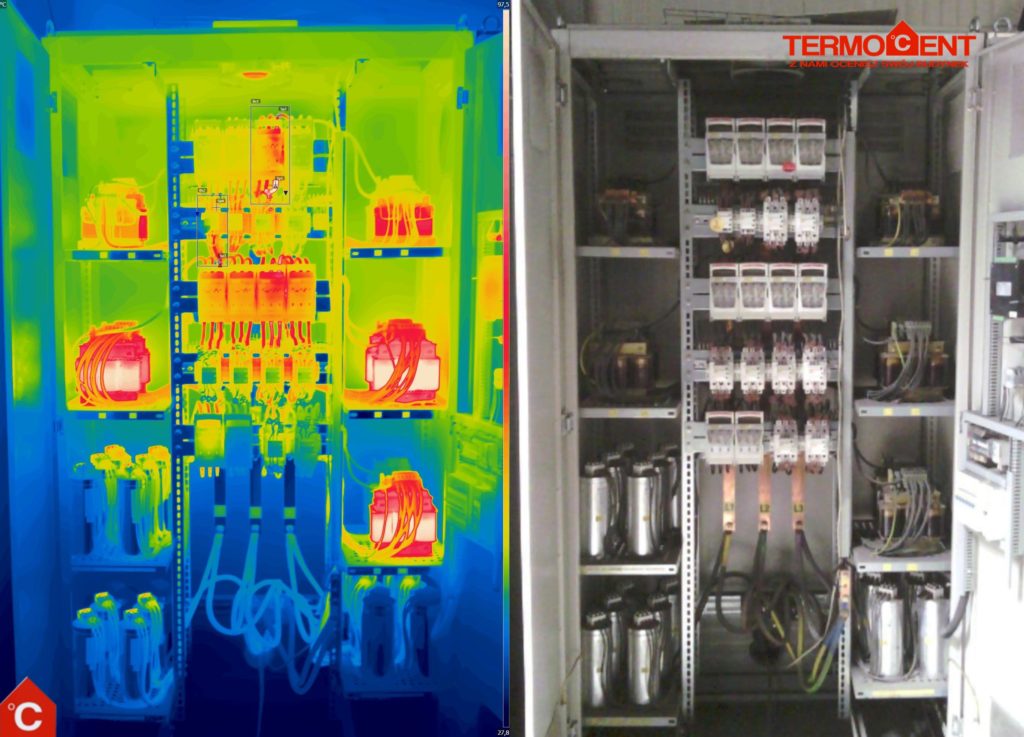
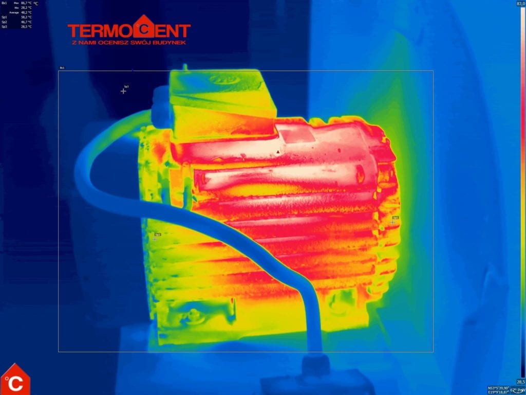
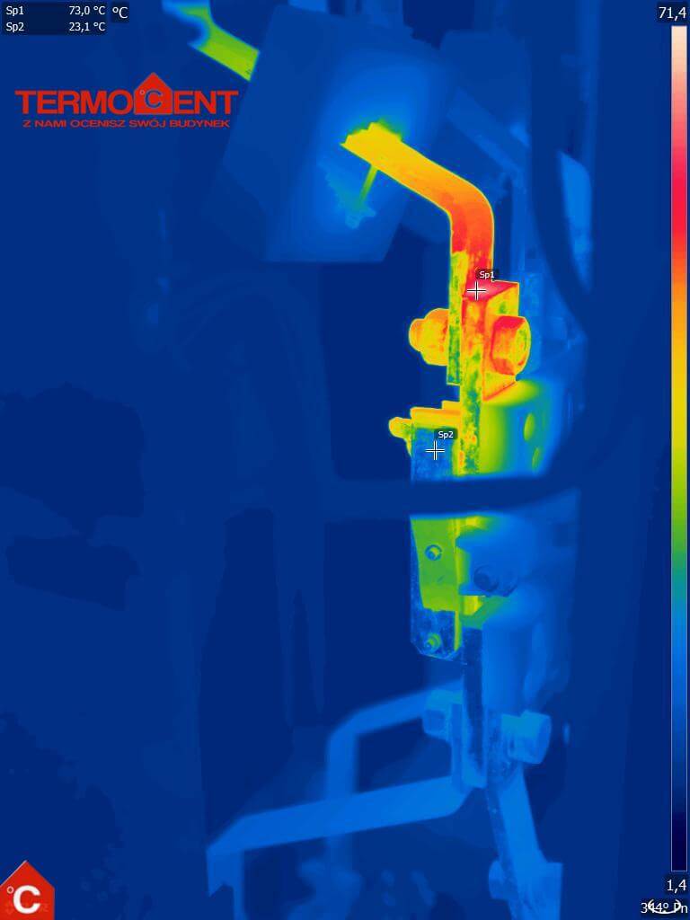
- In the event of a defect, photos of the irregularity are attached to the report,
- During the examination, we use a high-quality thermal imaging camera, which allows us to pinpoint the exact location of the defect.
- in accordance with the standard recommendations, the diagnostician should be independent of the ordering party (the so-called third party), that is, he must not be an employee of the company for which the test is carried out

The consequences of neglecting the electrical system – avoid fire!
– Too high a load causes too high a temperature, with consequent over-firing of the wires, and an increasing risk of fire. Any neglect of even the smallest conductor exposes installations and even the entire building to failure or fire.
– Malfunctioning electrical systems can contribute to the death of workers.
– The cost of repairs and production losses can reach several hundred thousand zlotys in a single incident. A complete combustion of the facility can occur, and losses can reach up to 10 million zlotys.
Conduct an inspection of the electrical system
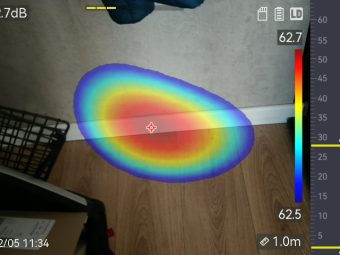
We use an ultrasonic detector and a thermal imaging camera to perform the survey in order to best inspect electrical equipment and installations. The examination is performed at a safe distance. Such a method allows for non-contact measurement and also quickly and effectively assess the condition of the tested installation. After the survey, a detailed report is prepared with the defects shown. Such a report will include detailed information about the tested object and electrical installations. We will provide instructions for the next inspection, as well as indicate the cause of the defect and describe how to remedy it.
Quotation for the service of thermal imaging of electrical installations
Poniżej przedstawiamy przykładową listę elementów często podlegających kontroli podczas badania termowizyjnego instalacji elektrycznej:
- Komora transformatora, transformator – ilość szt.
- Rozdzielnia RGnn – (np. 1 x 8 pól, 2 x 6 pól) – każde pole to szafa o wymiarach do 60×200 cm.
- Rozdzielnie wewnętrzne (np. wyłączniki nadprądowe itp.) – ilość szt.
- Sterowanie wentylatorami – ilość szt.
- Sterowanie przy maszynach – ilość szt.
- Gniazda trójfazowe – ilość szt. (kontrola dotyczy tylko tych gniazd, do których są podłączone urządzenia pobierające energię).
- Gniazda jednofazowe – ilość szt. (kontrola dotyczy wyłącznie gniazd obciążonych poborem energii powyżej 3 kW).
- Liczba stanowisk w akumulatorowni (prostowników) – ilość szt.
- Liczba silników o mocy powyżej 3 kW – ilość szt.
- Liczba pomp, kompresorów – ilość szt.
- Liczba paneli PV – ilość szt.
Price calculation method
- Komora transformatora – 3 punkty pomiarowe.
- Pole SN – 2 punkty pomiarowe.
- Pole NN lub szafa o wymiarach do 200 x 60 cm (każde drzwi do otwarcia) – 1 punkt pomiarowy.
- Stacja ładowania akumulatorów – 0,5 punktu pomiarowego.
- Silniki, pompy, kompresory – 0,5 punktu pomiarowego.
- Panel PV – 1 punkt pomiarowy.
Informacje dodatkowe
- Rodzaj instalacji, które mają zostać poddane kontroli.
- Liczba poszczególnych elementów (np. komory transformatorów, rozdzielnie, gniazda, maszyny itp.).
- Ewentualne specyficzne wymagania dotyczące kontroli.
With this information, we can tailor our offer to individual needs and guarantee professional implementation of the thermal imaging survey with the highest standards of TERMOCENT.
The process of performing a thermal imaging inspection of an electrical system
We perform measurements according to the guidelines (standards) of VdS 2851, VdS 2859 and DIN 54191. Examples of guidelines used in German standards (translation):
Technical guidelines (standard) Vds 2851 (excerpts):
3 Qualifications of the thermographer.
3.1. Introduction.
In order to make reasonable use of thermography as a means of monitoring electrical installation systems, the person using this measuring equipment must also meet certain requirements. In this context, the following problems can be distinguished:
a) Problems that can occur during thermographic recording.
b) Problems that must be solved when interpreting thermographic images.
These issues must not be ignored because “color images do not make a thermographic study. The person behind the camera is more important than the quality of the camera itself.
3.2. Taking a thermographic picture.
The thermographer must be able to recognize the factors affecting the test and take them into account accordingly. These include:
– possible thermal reflections,
– thermal effect of ambient radiation on the measured object (heating or cooling),
– distance to the object taking into account the geometric resolution of the camera used,
– emissivity of the observed surface.
3.3. Interpretation of thermographic images.
The special features of thermography are illustrated by the example of electrical thermography. Here, electrical devices are studied, which heat up differently depending on the load. The level of temperature generated depends on, among other things:
- load current flowing at the time of registration, and
- type and design of electrical equipment
3.4 Requirements for thermographers.
In order to describe the qualifications of a thermographer, it is necessary to clarify exactly what tasks the thermographer is expected to perform. At this point, it is necessary to distinguish between research
- which are used to carry out control tests (based on professionally performed thermography). Such follow-up surveys may be necessary after repairs or when weaknesses are identified after a thermographic inspection to be observed in the future .
- used to determine and assess the condition of the system, possibly in conjunction with the question of whether the system or its parts are likely to fail in the short term, etc.
The first mentioned check-up can certainly be carried out by a properly trained employee. Appropriate training is offered in the form of three- or four-day courses, for example, by the manufacturer of the apparatus.
The latter tests should be carried out by a professional thermographer who has the appropriate measuring equipment, as well as professional experience and basic theoretical knowledge. Due to rapidly changing technology, such a thermographer must undergo continuous training. External service providers often offer themselves as professional thermographers. If you want to be sure that the services offered by such a provider are indeed up to the appropriate level, you should request the appropriate certification.
4 The procedure for successful thermography:
4.1. Preparation. Thermographic studies should be well prepared for effective execution. The following points should be clarified beforehand (see guidelines in Appendix 1).
- Is the area or plant being surveyed visually accessible, i.e., is there good visibility to the relevant survey points? If not, it may be necessary to open the door and remove the covers (including transparent covers made of plastic or glass), provided this can be done safely during operation. Otherwise, thermography is not possible.
- Are there temperature specifications for the area or system under study that describe normal conditions or are there, for example, manufacturer specifications/standard values? Are comparative measurements from the past or from structurally identical systems available so that any measured temperature differences can be evaluated?
- Depending on your measurement needs, decide which electrothermography systems to use. Pyrometers are often sufficient for single-point measurements (e.g., post-assembly inspection measurements). If large areas are to be surveyed or serial surveys are to be carried out, a suitable thermographic camera should be used.
- In order to find the measurement points more easily, they should be photographed. Suitable cameras (such as a digital camera) should be prepared for this.
- Necessary work safety measures, required personal protective equipment, etc. for the area to be surveyed should be agreed in advance with a work safety specialist. In addition, additional work equipment such as ladders, electrical power, etc. may be required.
Appendix C – Minimum requirements for relevant camera systems (normative)
The following technical data of FPA camera systems (focal plane array camera systems) represent the state of the art. They ensure consistent and comparable quality of measurement results in the context of the test series and are therefore mandatory for camera selection.
- ambient temperature (application range): – 10°C to +40°C
- Measurement range: – 20°C to +500°C
- Accuracy/measured value: ±2% or 2K
- Spectrum: LW 7.5 µm or MW 3-5 µm
- Geometric resolution for 20º – 25º FOV lens: ≤ 2 mrad (smallest measurable object: ≤ 3mm) or min. 500:1
- Image: artificial color
- bolometric matrix: min. 320 x 240 pixels
- Adjustable measurement parameters: Emissivity, reflected ambient temperature
- Temperature range scale: 1 measuring point (spot), 1 isotherm, 1 measuring point, automatic hotspot search function, freeze function
- Measurement management: IR radiometer – recording and evaluation of the recording, operation of external or rotating display
Undoubtedly, the advantage of electro-thermal imaging is the ability to perform high-voltage testing of power equipment under normal operating conditions and standard loads while maintaining a safe distance.
More frequent fire inspections may be required for cases where there may be a greater risk of operating electrical equipment and installations, depending on environmental conditions. These include locations where there is a risk of electrical shock, fire or explosion due to degradation, as well as locations with both low- and high-voltage installations.
You may also be interested in: LOCATING A RUN OR LEAK IN THE WATER AND CO