Thermal imaging surveys of electrical installations have become a key diagnostic tool, especially in the context of insurers’ requirements. They not only help identify potential hazards, such as overheating of components, but also increase the chances of receiving compensation in the event of an insurance incident. Below is a detailed guide on how to prepare for such a survey.
Why do insurers require thermal imaging surveys of electrical systems?
Regular thermal imaging surveys allow:
- Identify early signs of technical problems, such as loose (untightened) connections, overloaded circuits, or damaged insulation,
- Prevent costly breakdowns and fires,
- Meet legal and insurance requirements,
- Gain insurance benefits through better risk assessment by insurers.
For industrial companies, warehouses or office buildings, electrical failures can lead to downtime and large financial losses. Regular inspections help prevent such situations. Keep in mind that inspections are recommended once a year, and up to four times a year for installations exposed to harmful load factors or the environment.
Guidelines for thermographic testing in Poland – how to meet insurers’ requirements
In Poland, there are no explicit regulations mandating regular thermal imaging inspections of electrical switchgear in business operations. Nevertheless, insurance companies increasingly require them to comply with German VdS (Verband der Sachversicherer) standards, including VdS 2851, VdS 2859 and VdS 2860. There are also situations where the less typical ASTN qualification, which applies only in the US, is expected. The VdS documents, marked with different numbers, contain guidelines and documentation templates for thermographic testing of electrical installations and rules for the prevention of damage associated with their use. Each of these documents is developed by the German organization VdS Schadenverhütung GmbH, which specializes in damage prevention and technical safety. In order to respond to these challenges, the Polish Society of Thermography Engineers and Technicians (SIiTT), established in 2022, has developed its own guidelines, PST 6021:2024, which are intended for professionals qualified in thermographic testing and can serve as a tool for brokers and insurance companies to evaluate reports. The PST 6021:2024 guidelines are based on a broad set of technical and normative documents, including:
- Ordinance of the Minister of Energy, dated August 28, 2019, regarding the rules of safety and occupational health in the use of energy equipment.
- International Dictionary of Legal Metrology Terms, published by the General Office of Weights and Measures.
- ISO 18434-1:2023, which treats the monitoring and diagnosis of machinery using thermography.
- ISO 18436-7:2014 (E), relating to the certification of personnel using thermography for diagnostic purposes.
- PN-EN ISO/IEC 17025 standard, introducing general requirements for the competence of testing laboratories.
- EN ISO 9712:2022-09 standard for certification of nondestructive testing personnel.
- DIN 54191, discussing non-destructive thermographic testing of electrical equipment.
- DIN EN 50110-1 (VDE 0105-1) standard for the operation of electrical installations.
- DIN VDE 1000-10 (VDE 1000-10), presenting requirements for workers in the electrical engineering sector.
- VDE 0105 standard, part 100, which contains general requirements for the operation of electrical installations.
- VDI guideline 2878, sheet 1, describing the use of thermography in diagnostics and maintenance.
- VdS 2851 guidelines, outlining practical tips for non-contact temperature measurement by thermography.
- VdS guideline 2858, discussing the use of thermography in electrical installations to prevent damage and enhance workplace safety.
- VdS Guidelines 2859 Appendix C, presenting the minimum requirements for camera systems used in testing.
- VdS guideline 2860, sample report of thermographic examination of electrical installation.
- VdS guideline 2871 Guidelines for testing electrical installations in accordance with SK clause 3602.
- VdS guideline 3447 Information sheet for testing electrical installations in accordance with clause SK 3602.
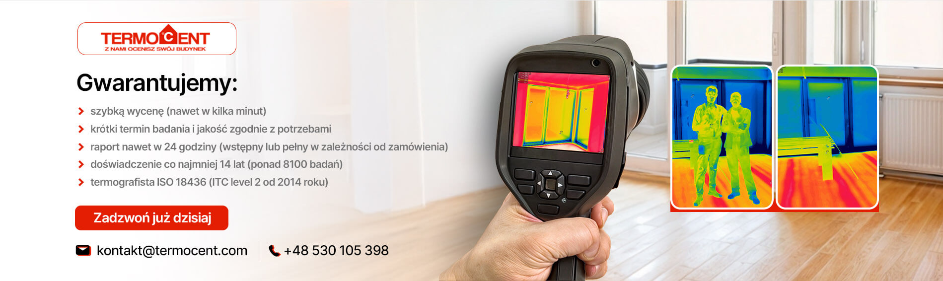
If you are looking for professionals who will reliably conduct thermal imaging measurements of the electrical system and detect all weak spots, bet on TERMOCENT. We have all the required licenses. We employ experienced thermographers who accurately interpret thermograms.
STANDARD TERMOCENT meets and exceeds the requirements of the guidelines written in VdS or other documents. We operate throughout the country. We can offer short waiting times for examination, competitive prices and a partnership atmosphere of cooperation.
How to prepare for a thermal imaging survey of electrical installations?
Preparing for the survey is key to making sure it goes smoothly and meets both technical and formal expectations. Here is a brief guide to help you prepare properly for the survey.
A. Choosing the right company
Insurers specify specific requirements that must be met for the audit report to be accepted. The requirement is that the survey be conducted by:
- Independent third parties with appropriate qualifications, such as those in accordance with ISO 18436-7
- the person performing the measurement was a Thermographer with a minimum of Energy Group 1 qualification,
- a company with equipment that meets standards and guidelines, such as VdS 2859, which define the minimum technical parameters of thermal imaging cameras.
B. Provide access to installations
In order for the test to run smoothly, it is necessary to ensure access to key plant components during the test. It is essential to be able to open control cabinets and switchgear during the test. It is worthwhile to take care in advance to clean up the space around the equipment under test, which may impede the test and access to the components under test.
C. Maintaining an adequate load
The test must be carried out at the plant’s normal load, which is usually at least 30% of its nominal capacity. On the day of the test, it is a good idea to make sure that all appliances that are normally on are operating in their standard mode.
Why commission a thermal imaging survey from TERMOCENT?
If you’re looking for professionals to comprehensively and reliably conduct thermal imaging measurements of electrical systems, choose TERMOCENT. Our company not only meets, but also exceeds the requirements of insurers, guaranteeing the highest quality of service.
Why choose TERMOCENT?
- Experience and Qualifications: We are staffed by qualified thermographers
with Level 2 certifications according to ISO 18436-7:2008 and Energy Group 1 unrestricted D1 and E1 qualifications. - Precision equipment: Our thermal imaging cameras are regularly calibrated to ensure the accuracy of measurements and reliability of results. Our company uses modern equipment such as FLIR E95 cameras and the best T1020 camera available on the market, which feature high resolution and thermal sensitivity for precise measurements.
- Compliance with standards: STANDARD TERMOCENT performs tests in accordance with APSAD D19, VdS guidelines, among others – recognized in our region – which guarantees full acceptance of reports by insurers.
- Nationwide coverage: we operate nationwide, offering short lead times.
- Competitive pricing: We provide fair customized pricing.
With TERMOCENT, you can be sure that your electrical installation will be tested by independent experts, and that the results will not only comply with guidelines or standards, but
and practical for you.

The best thermal imaging camera available on the market
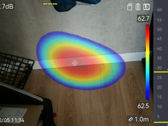
To carry out a thermal imaging study, a specialized camera is required to record the thermal radiation emitted by the components of the electrical system. The camera takes a picture – the so-called thermogram – showing the temperature distribution in the various parts of the installation. Analysis of the thermogram makes it possible to determine whether the temperature of each element of the installation is within a safe range.
For some time now, we have been using the best FLIR T1020 thermal imaging camera available on the market for commercial applications. This allows us to offer our customers thermal imaging at the highest matrix resolution of 1024×768 (UltraMax as high as 2048×1536) and guarantee precise measurements even in adverse conditions. The UltraMax technology used in the T1020 camera allows us to additionally increase the number of temperature points by four times and make the thermograms we interpret more detailed.
The high quality of the lens of the FLIR T1020 camera allows us to obtain great quality images from both very short and long distances, even twice as far as with typical equipment. Thanks to the many available features of our camera, we are able to see all the details, which will serve us to meticulously analyze the problem occurring in construction facilities and to effectively detect all the relevant temperature differences in the thermograms.

Inspection reports
With thousands of completed projects, we know how important it is to accurately interpret thermograms. Our reports not only indicate the locations of potential hazards, but also provide useful guidance for maintenance or investment activities.
We carry out inspection reports for our clients in two options to choose from:
- BASIC OPTION (report): preparation of a report for the Employer with a list of all equipment examined and interpretation of thermal imaging images of all significant defects in accordance with the TERMOCENT standard.
- EXTENSIVE REPORT (report + report): preparation of a report for the Ordering Party with a list of all devices examined and interpretation of thermal images of all significant defects according to the TERMOCENT standard, as well as a report containing at least one image (thermogram
with interpretation) for each device examined.

Contact us and we will send you a sample report or report
of the survey conducted for your review!
Priority weight defects
Detecting a defect in the device during the inspection, our specialist, thanks to 15 years of experience, gives the appropriate priority, which determines how quickly corrective action should be taken.
An example of stickers used in the TERMOCENT standard as of 2018:

Stickers with the appropriate priority are affixed during the inspection to the defective device. In the report or report sent after the inspection, the Purchaser also receives information on how urgent it is to repair the tested device.
 |
 |
 |
 |
Tested elements during the inspection
Any facility with an electrical system on its premises is required to regularly inspect its condition. This is particularly important in the case of manufacturing and processing plants, warehouses, office, service and retail facilities or facilities of a nature, sports, cultural and entertainment.
In order to prepare a precise quote for you for a thermal imaging survey of the electrical system, we ask you to provide us with an approximate number of system components to be inspected. Based on the information provided, we can prepare a detailed quote.
The following is a sample list of items often inspected during a thermal imaging survey of an electrical system:
- Transformer chamber, transformer – number of pcs.
- RGnn switchgear – (e.g., 1 x 8 bays, 2 x 6 bays) – each bay is a cabinet with dimensions up to 60×200cm
- Internal switchgear (containing, for example, overcurrent circuit breakers, etc.) – number of pcs.
- Control of fans – number of pcs.
- Control at machines – number of pcs.
- Three-phase outlets – number of pieces. (the control applies only to those sockets to which power-consuming devices are connected).
- Single-phase outlets – number of pieces. (The control applies only to outlets loaded with energy consumption of more than 3 kW).
- Number of positions in the battery room (rectifiers) – number of pcs.
- Number of motors with a power of more than 3 kW – number of pcs.
- Number of pumps, compressors – number of pcs.
- Number of PV inverters and installation capacity in kWp – number of pcs.
Watch the video and learn what a thermal imaging survey of an electrical system looks like in practice!